Introduction
This previous article provides an overview of the FortiGate SD-WAN solution. This article will focus on the nuts and bolts of the actual configuration used to establish SD-WAN between two FortiGates. In addition to that, it will conclude with a video showing this topology with/without SD-WAN so you can see its true potential.
There is an assumption that the reader of this article has a NSE 4 (or higher) understanding of the FortiGate platform.
Topology
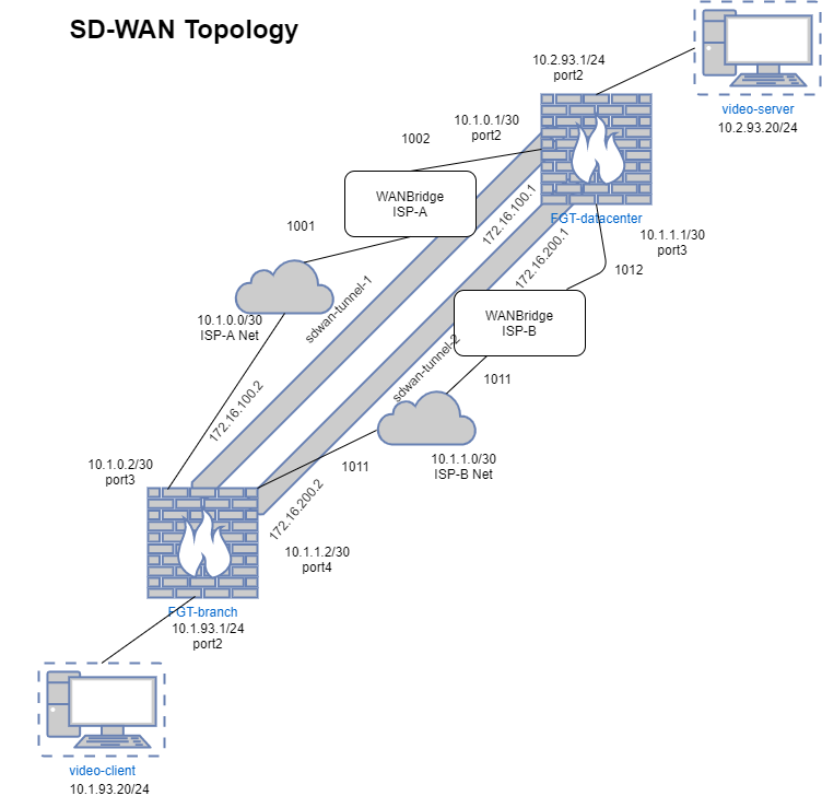
The topology in this article is very simple as it establishes connectivity directly between two sites protected by FortiGate. It is not indicative of typical enterprise deployments, however it is simple enough to demonstrate the capabilities of SD-WAN between two FortiGates.

To simulate a network sensitive application, video will be streamed between two hosts. One host will be the client and the other will be the server of the video. There will be a mechanism within the topology to simulate unfavorable network conditions while the streaming occurs.
Components
There are a small number of components that make up this topology.
Windows 7 Clients
The windows clients will be running VLC media player in order to simulate the client and server functions for video streaming. Streaming will occur over HTTP/8080. They will have a simple configuration with no firewalls enabled and their default gateway pointing to their corresponding FortiGates.
FortiGates
The FortiGates will have direct connectivity to each other with no routes in between. They will have established network connectivity and an overlay IPSec network that rides on top.
SD-WAN will be configured on both FortiGates to perform intelligent path routing on the video streaming traffic. The FortiGates will be connected through devices that emulate poor network conditions to demonstrate the functionality of SD-WAN.
WANBridge
The WANBridge is an open source non-maintained project that allows for emulation of poor network conditions by modifying the bandwidth, packet loss and latency of a network flowing through the device. This device functions as a bridge and is inserted as a transparent “bump in the wire” between two network devices. This allows for no explicit routing changes necessary in order to add capability is emulating poor network conditions.
Configuration
Now that the components have been identified, the configuration of these components can be completed to simulate a network environment. This section is will mostly focus on the configuration of the FortiGate related devices. However, non-FortiGate devices will have a brief overview of their configuration in relation to this environment.
FortiGate
The FortiGate is the most important piece of this environment as will be providing the SD-WAN functionality within the topology. There is an assumption that the basic network connectivity has been configured according to the diagram referenced at the beginning of this post. This will establish the transport network that will be used to build the overlay network on top of.
Overlay Network
As referenced in the previous article, the overlay network is a critical component to the function of SD-WAN. This is due to abstract the transport of data between the two endpoints so that any media can be used for transport as long as there is end-to-end connectivity between the FortiGates. In this case, the overlay network will be comprised of IPSec Tunnel VPNs between the two FortiGates.
For simplicity sake, it is recommended to configure the VPNs via the CLI as the default settings associated with the VPN creation wizard in the WebGUI will require changes to work with SD-WAN.
Some components to highlight from both of these configurations are the following:
- In the phase1-interface definition, the FortiGate has the “exchange-interface-ip” command set allow the remote FortiGate to dynamically learn its IP address during the Phase1 negotiation of the VPN. This is tremendously useful for establishing a dynamic routing protocol across the VPN tunnel and the remote side is using a dynamic (dial-up) type VPN.
- In the phase1-interface definition, the FortiGate has the “set tunnel-search nexthop” parameter configured in order to force the FortiGate to use its routing table instead of IPSec phase2 Security Associations when choosing the IPSecVPN tunnel to route the traffic out of. This is useful for when you have multiple IPSec VPNs defined on a single interface. This is only configurable when “set net-device disable” is set within the configuration.
- IP addresses are defined on the VPN interfaces. The purpose of this is to allow the FortiGate to define an IP address to use when it is performing its SLA health check across the VPN interfaces within the SD-WAN configuration.
FGT-branch
Below is the configuration of the IPSec VPN configuration for FGT-branch.
VPN (Overlay) Configuration
config vpn ipsec phase1-interface
    edit "vpn-isp-a"
        set interface "port3"
        set peertype any
        set net-device disable
        set exchange-interface-ip enable
        set proposal aes128-sha1
        set dhgrp 14
        set remote-gw 10.1.0.1
        set tunnel-search nexthop
        set psksecret ENC DqV78qFjD/DsZlhwr5Psq6HM9+ZSo3WbSTQEqsdeTUG/uCAvSduEsU                                                                                                 ce1/L4lFBukAhBDha9NqRaGRFHMayi7Y8D/Duk/zWW3PEJcBli70wn+HBFiKMtH4C4iszucjBKJiXFUb                                                                                                 C8/U7UIlnLDGcse8/q1/YZEtimdmwe0vQ4rid2rzyQJAv6vZdgxPri5eZtcbO0Kg==
    next
    edit "vpn-isp-b"
        set interface "port4"
        set peertype any
        set net-device disable
        set exchange-interface-ip enable
        set proposal aes128-sha1
        set dhgrp 14
        set remote-gw 10.1.1.1
        set tunnel-search nexthop
        set psksecret ENC z+mQuCm4Ow73OU7ybBMVhbKl7zSCqNSdHMvRP+fXOQHo1CgrPtd54N9OgP+jPg4QsUMtigMWyiYnbSta6Exwbp2ENbGWf/hbQUbE0ss4zsWEvMTNW5u96IlbrFCD4YecfCdH6i4Yrl1349rC9/aKnYSgtiB17MJyGQaq7ASzxK4ygjfcORjgfqO+qELRIOYYWt6tQA==
    next
end
config vpn ipsec phase2-interface
    edit "vpn-isp-a_p2"
        set phase1name "vpn-isp-a"
        set proposal aes128-sha1
        set dhgrp 14
    next
    edit "vpn-isp-b_p2"
        set phase1name "vpn-isp-b"
        set proposal aes128-sha1
        set dhgrp 14
    next
end
VPN Interface Configuration
config system interface
    edit "vpn-isp-a"
        set vdom "root"
        set ip 172.16.100.2 255.255.255.255
        set type tunnel
        set remote-ip 172.16.100.1 255.255.255.255
        set snmp-index 6
        set interface "port3"
    next
    edit "vpn-isp-b"
        set vdom "root"
        set ip 172.16.200.2 255.255.255.255
        set type tunnel
        set remote-ip 172.16.200.1 255.255.255.255
        set snmp-index 7
        set interface "port4"
    next
end
FGT-datacenter
Below is the IPSec VPN configuration for FGT-datacenter.
VPN (Overlay) Configuration
config vpn ipsec phase1-interface
    edit "vpn-isp-a"
        set interface "port3"
        set peertype any
        set net-device disable
        set exchange-interface-ip enable
        set proposal aes128-sha1
        set dhgrp 14
        set remote-gw 10.1.0.2
        set tunnel-search nexthop
        set psksecret ENC aBbmpQ4UVNCWuXUrlzzIPW0zRlU/QZuymPQ3bQzDwMGQHV7eui9wH2                                                                                                 /pdIjDSAQwFlcf5cfyMD3GwyikqL4/nxQcAUwbwoxxfb7EZpiMSOJ7+pG3PXWEIbNTdGDdeLEgjKXmcp                                                                                                 Vn46eOUFSha51n8DdhdyKen0H6naemU+g41IAV6OfxjVjidPFbep71DrbMo/DS6Q==
    next
    edit "vpn-isp-b"
        set interface "port4"
        set peertype any
        set net-device disable
        set exchange-interface-ip enable
        set proposal aes128-sha1
        set dhgrp 14
        set remote-gw 10.1.1.2
        set tunnel-search nexthop
        set psksecret ENC vJc9qq1qCzX5QfpAu+wWGbrgSu0B+D0q6TmeQABxSPCwiuPZtzpcQmfM8w0YROHR3DrIR1HGk3BPfyAy2MLXgdAJK/UcYblOQNM3aj+ZmtAtlf7vtd9nOK7U6Nv4ohBzSmYnCNUgSlja1ZJ1dHFKnrfkKERS8c00DulCyBRSftKbndEMnZAAqj982iAgc4bA+ZYc4A==
    next
end
config vpn ipsec phase2-interface
    edit "vpn-isp-a_p2"
        set phase1name "vpn-isp-a"
        set proposal aes128-sha1
        set dhgrp 14
    next
    edit "vpn-isp-b_p2"
        set phase1name "vpn-isp-b"
        set proposal aes128-sha1
        set dhgrp 14
    next
end
VPN Interface Configuration
config system interface
    edit "vpn-isp-a"
        set vdom "root"
        set ip 172.16.100.1 255.255.255.255
        set type tunnel
        set remote-ip 172.16.100.2 255.255.255.255
        set snmp-index 6
        set interface "port3"
    next
    edit "vpn-isp-b"
        set vdom "root"
        set ip 172.16.200.1 255.255.255.255
        set type tunnel
        set remote-ip 172.16.200.2 255.255.255.255
        set snmp-index 7
        set interface "port4"
    next
end
SD-WAN
After the VPNs have been configured, the SD-WAN configuration can occur. This process consists of defining a virtual SD-WAN interface that will be comprised of the components in the overlay network. In addition to that, SLAs, SD-WAN rules, routes and firewall rules will be defined in order to enable this capability.
Please note, in the VPN configuration, no static routing or firewall rules were defined. This is due to the nature that these routes and rules will be defined using the virtual SD-WAN interface instead of the individual VPN interfaces.
Some components to highlight from both of these configurations are the following:
- The SD-WAN rules are only defined on the FortiGate-branch. This highlights that SD-WAN does not require a controller to coordinate this functionality across all FortiGates and instead can occur from the source of the traffic.
- The “sla-*-log-period” is a useful command to configure the FortiGate to make a interim log for the current state of the SLAs.
FGT-branch
Below is the SD-WAN configuration for the FGT-branch.
SD-WAN Interface Configuration
config system virtual-wan-link
    set status enable
    config members
        edit 1
            set interface "vpn-isp-a"
        next
        edit 2
            set interface "vpn-isp-b"
        next
    end
end
SD-WAN Service Level Agreement Configuration
config system virtual-wan-link
    config health-check
        edit "remote"
            set server "10.2.93.1"
            set failtime 2
            set recoverytime 10
            set sla-fail-log-period 60
            set sla-pass-log-period 60
            set members 1 2
            config sla
                edit 1
                    set latency-threshold 75
                next
            end
        next
    end
end
SD-WAN Rule Configuration
config system virtual-wan-link
    config service
        edit 1
            set name "best_latency"
            set mode priority
            set dst "all"
            set src "all"
            set health-check "remote"
            set priority-members 1 2
        next
    end
end
Static Route Configuration
config router static
    edit 2
        set dst 10.2.93.0 255.255.255.0
        set distance 1
        set virtual-wan-link enable
    next
end
Firewall Rule Configuration
config firewall policy
    edit 4
        set name "outbound sd-wan"
        set srcintf "port2"
        set dstintf "virtual-wan-link"
        set srcaddr "all"
        set dstaddr "all"
        set action accept
        set schedule "always"
        set service "ALL"
    next
    edit 5
        set name "inbound sd-wan"
        set srcintf "virtual-wan-link"
        set dstintf "port2"
        set srcaddr "all"
        set dstaddr "all"
        set action accept
        set schedule "always"
        set service "ALL"
        set comments " (Copy of outbound sd-wan) (Reverse of outbound sd-wan)"
    next
end
FGT-datacenter
Below is the SD-WAN configuration for the FGT-datacenter.
config system virtual-wan-link
    set status enable
    config members
        edit 1
            set interface "vpn-isp-a"
        next
        edit 2
            set interface "vpn-isp-b"
        next
    end
end
config system virtual-wan-link
    config health-check
        edit "remote"
            set server "10.1.93.1"
            set sla-fail-log-period 60
            set sla-pass-log-period 60
            set members 1 2
        next
    end
end
config router static
    edit 2
        set dst 10.1.93.0 255.255.255.0
        set distance 1
        set virtual-wan-link enable
    next
end
config firewall policy
    edit 4
        set name "outbound sd-wan"
        set srcintf "port2"
        set dstintf "virtual-wan-link"
        set srcaddr "all"
        set dstaddr "all"
        set action accept
        set schedule "always"
        set service "ALL"
    next
    edit 5
        set name "inbound sd-wan"
        set srcintf "virtual-wan-link"
        set dstintf "port2"
        set srcaddr "all"
        set dstaddr "all"
        set action accept
        set schedule "always"
        set service "ALL"
        set comments " (Copy of outbound sd-wan) (Reverse of outbound sd-wan)"
    next
end
Windows 7 Host
The networking configuration on the Windows 7 hosts is very straight forward. Each Windows 7 host has its corresponding FortiGate set as its default gateway.
WANBridge
The WANbridge host serves as a transparent bridge between the FortiGates that can simulate non-ideal conditions on the network. This host is used to add latency and packet loss to the network link to cause the SD-WAN functionality from the FortiGate to detect this condition and route over better performing link. For the purpose of demonstration, WANBridge will be used to simulate poor network conditions with a packet loss of 4% and a latency of 400 milliseconds.

Demo
The demo will show two scenarios. The first will be a scenario where poor network conditions are simulated on the primary network link and SD-WAN is not enabled. The second scenario is when the same poor network conditions are simulated on the primary link, but with SD-WAN enabled, the firewall quickly chooses a better link candidate with little to no interruption to the user.
Please let me know your thoughts on this content in the comments below.
First time reading about Fortinet SDWAN.Your article has been quite informative!! Keep up the good work mate.
can we do a hub/spoke topology with this?
Hi Matt,
Yes, a hub and spoke topology can be done with this. I will focus on this more and create an article about this within the next couple of weeks. If you need any guidance before then, just let me know and I can send the basic configurations to get that up and running to your email.
Hi,
I would like to configure a more complex scenario but I cannot find any good articles which are showing me how to do it… maybe you have some good tips? 😉
two location are connected via a directlink (fiber cable). This should be the primary line to exchange data.
Both location has also dedicated MPLS connection and this line should be used as backup to exchange data.
And both location must be reachable of course from HQ.
How must be the setup? Do you have some good tips for me?
Regards,Timo
Hi Timo,
I am quite a bit behind on responding. You can email me at jtorian@historiantech.com if you still need help on this.