
The previous post in this series provides an introduction to Network Access Control and the components of the security fabric oriented solution of Fortinet that enables these capabilities in a single platform. This post will focus on the leveraging device identifiers to categorize devices connecting in through the FortiSwitch and assigning them the correct access based on those identifiers.
Dynamically Controlling Access based on Device
There is ample documentation on integrating the FortiGate and FortiSwitch so the assumption is that the baseline integration between those two products has been completed. In this particular method, the only two components needed to facilitate this type of control are the following devices:
- FortiGate
- FortiSwitch
With that assumed, this guide will pick up where the FortiSwitch is being managed by a directly connected (Layer 2 adjacent) FortiGate.
Preparing the FortiGate for NAC Policies
Prior to jumping into the configuration of the NAC policies on the FortiGate, some foundational settings need to be configured on the FortiGate. Those items are:
- Creating the Onboarding VLAN
- Running the NAC Policies Wizard
Creating the Onboarding VLAN
One of the fundamental concepts associated with applying NAC policies to the FortiSwitch is the use of an Onboarding VLAN for unidentified devices. This VLAN typically has restricted access and may even be configured with a captive portal to provide a splash page the user must acknowledge prior to accessing resources on the network. It is typical to assign a routable subnet to this VLAN for minimal access to validate the user via a network service as well as provide restricted access to the Internet.
An example of a configuration of the onboarding VLAN is shown in the screenshot below:
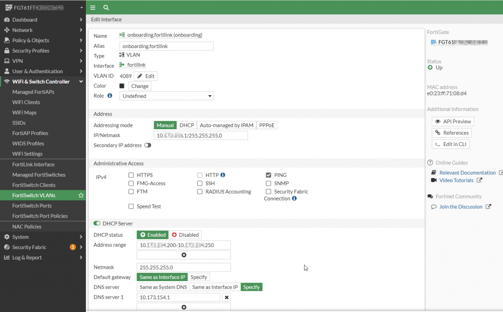
Figure 0. – Screenshot of the onboarding VLAN configuration
The corresponding CLI associated with this interface is as follows:
config system interface
    edit "onboarding"
        set vdom "root"
        set ip 10.A.B.1 255.255.255.0
        set allowaccess ping
        set description "NAC Onboarding VLAN"
        set alias "onboarding.fortilink"
        set security-mode captive-portal
        set security-exempt-list "onboarding-exempt-list"
        set device-identification enable
        set snmp-index 22
        set switch-controller-access-vlan enable
        set switch-controller-feature nac
        set interface "fortilink"
        set vlanid 4089
    next
end
Running the NAC Policies Wizard
By default, FortiLink should automatically provision its interface with VLANs assigned to a specific purpose. One of those VLANs is called “onboarding” which is used to assign a connected device that has not been identified. This VLAN is typically configured with restrictive firewall policies to limit the amount of access that is available while connected to this VLAN.
In the event that the NAC policies are not automatically configured for this onboarding VLAN, there is a wizard driven process to enable this configuration. This is shown in the steps below:
- Click on “WiFi & Switch Controller | NAC Policies”
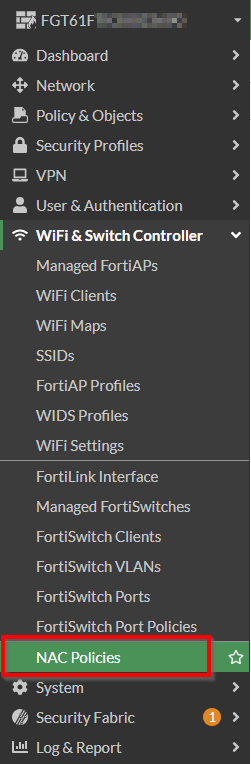
Figure 1. – Screenshot of the navigation pane with “NAC Policies”
2. Click on “Configure NAC Settings” on the NAC policies wizard dialog box
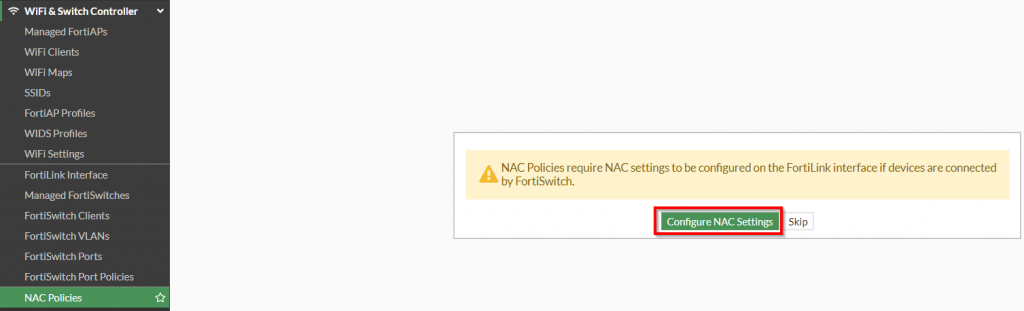
Figure 2. – Screenshot of the “NAC Policies” wizard
3. Choose your existing FortiLink interface | Choose the applicable “Onboarding VLAN” | Enable “Bounce Port” | Click “Next”
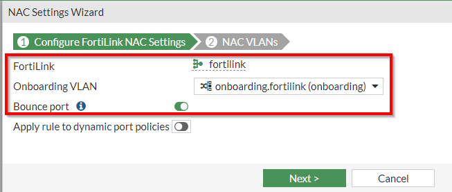
Figure 3. – Screenshot of the first page of “NAC Settings Wizard”
4. Leave the other settings as default | Click “Submit”
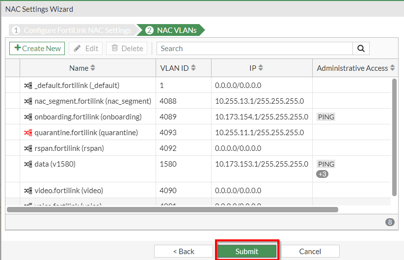
Figure 4 . – Screenshot of the second page of “NAC Settings Wizard”
5. Once that has been completed, you should have an entry under the NAC Policies as shown in the screenshot below:
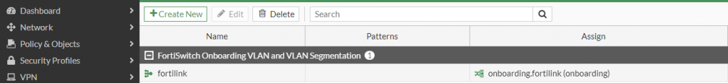
Figure 5. – Screenshot of the resultant entry after NAC Settings Wizard completion
Creating the NAC Policy based on Device
NAC policies can be created on a multitude of characteristics. When creating the NAC policy for the device, the following characteristics can be evaluated:
- MAC Address
- Hardware Vendor
- Device Family
- Type
- Operating System
- User
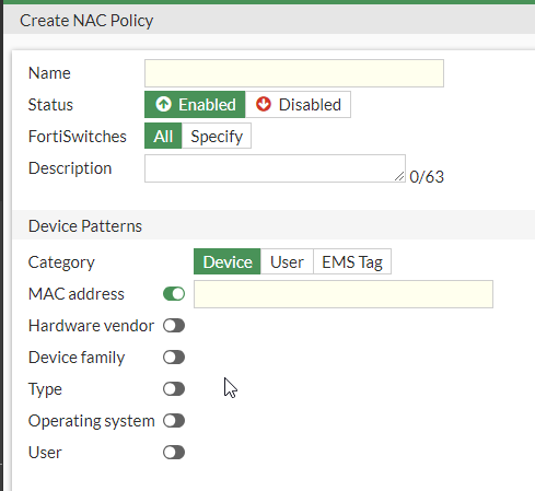
Figure 6. – Screenshot of the Device NAC Policy
The FortiGates ability to determine these values for these characteristics is facilitated through the use of the “device detection” feature on the FortiGate and FortiSwitch. With this functionality enabled, the Fortinet solution can passively identify what type of device is connecting to the infrastructure (FortiSwitch) and subsequently, create a policy to perform some type of action based on this information.
Example NAC Policy – Matching based on MAC Address
To demonstrate this capability, let’s go through a simple scenario to match based on the MAC address of the connecting device. To identify the MAC address of the device, we can leverage the DHCP monitor in the FortiOS GUI:
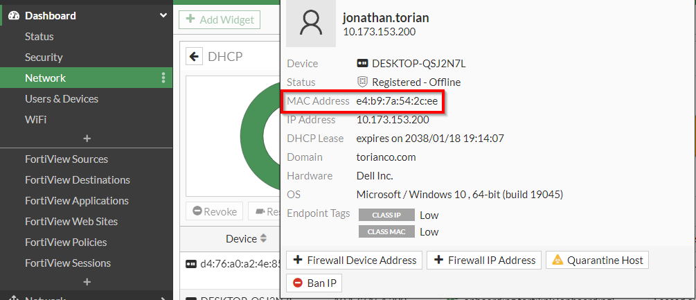
Figure 7. – Screenshot of the DHCP Monitor highlighting the MAC address of the endpoint
Now that we have the MAC address, we can use this information to create a NAC policy that will allow access to a particular VLAN when this particular MAC address connects to the FortiSwitch. To create this policy, follow the steps below:
- Navigate to “WiFi & Switch Controller | NAC Policies” | “Click ‘Create New'”
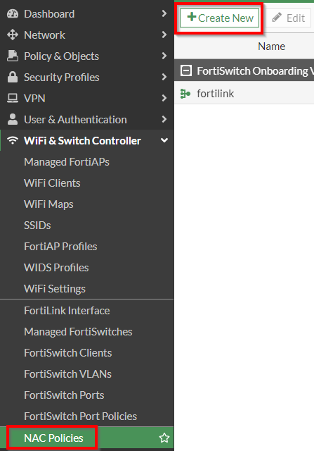
Figure 8. – Screenshot of Navigation pane highlighting NAC Policies
2. In the “Create NAC Policy” dialog populate the following fields | Click “OK”:
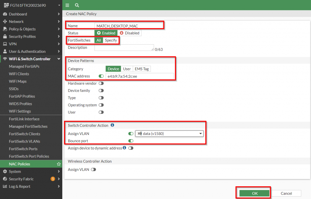
Figure 9. – Screenshot of the “Create NAC Policy” dialog
Note: The MAC Address field also supports “wildcard” MAC addresses if you want to apply this policy based on partial MAC address matching. Details of this is covered in the following link.
Note: Bounce Port being enabled is necessary to force the connecting device to lose and re-establish the physical link to reinitiate the DHCP process and gather the new IP address of the assigned VLAN. Keep in mind in virtual environments that the link status may not be propagated to a virtual host and subsequently may not learn the new IP address scheme of the VLAN.
3. The resultant policy should reflect the following:
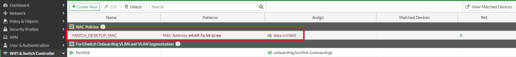
Figure 10. – Screenshot of the resultant “NAC Policies”
Configure the FortiSwitch Port for NAC Policies
Now that the NAC policy is in place, the FortiSwitch must be configured to apply it to its ports. Fortunately, this is not a global setting and the FortiSwitch can be configured to apply this on a per-port basis. This allows for a phased approach to deploy these settings without impacting any other production ports. To apply this to a single port, follow the steps in the procedure below:
1. Click on “WiFi & Switch Controller | FortiSwitch Ports”
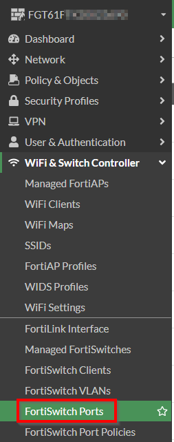
Figure 11. – Screenshot of the “Navigation Pane” to select FortiSwitch Ports
2. Right click the “Mode” column for a port to enable this on | Select “Mode | NAC”
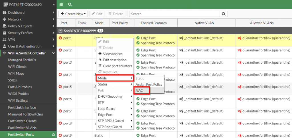
Figure 12. – Screenshot of enabling the “NAC” mode on a port in the FortiSwitch
3. Below is the resultant port configuration with the NAC setting enabled:
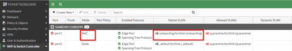
Figure 13. – Screenshot of the resultant FortiSwitch configuration with NAC mode enabled on the port
Please Note: Once NAC mode has been enabled, the native VLAN changes to “onboarding.fortilink” and is not able to be modified.
Please Note: Multiple ports can be selected by pressing “Ctrl+Click” or “Shift+Click” to apply the NAC mode to.
Configuring Access through the Firewall
Once the FortiSwitch ports have been configured to participate in NAC, the last step is to make sure the proper access for each VLAN is defined in the firewall policies. Below is an example policy that could be used to grant access to both the onboarding VLAN and the v1580 VLAN once the device has been properly identified.
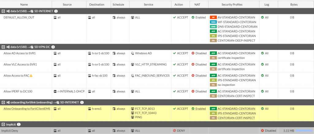
Figure 14. – Screenshot of the FortiGate firewall policy with access for onboarding and v1580
Validating the Network Access Control
Now that the policy is in place, you can connect the device with the assigned MAC address to the configured port and confirm that it is assigned to the correct VLAN per the NAC policy. The most common way to validate that the network access control policy has taken effect will be validation from the user. However, there are built-in ways to validate this from the FortiGate.
Viewing the Matched NAC Devices
Under the “NAC Policies” section of the FortiGate, you can view the “Matched Devices”. To accomplish this, follow the procedure below:
1. Under “WiFi & Switch Controller | NAC Policies” | Click “View Matched Devices”

Figure 15. – Screenshot of the “View Matched Devices” button in the FortiOS UI
2. If there is a match, a row should be present highlighting the “Matched NAC Policy” and “Assigned VLAN”
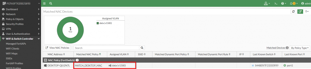
Figure 16. – Screenshot of the result of matched devices for the NAC policy
More information can be gathered by highlighting the host and seeing all of the telemetry learned from the device identification of the FortiGate:
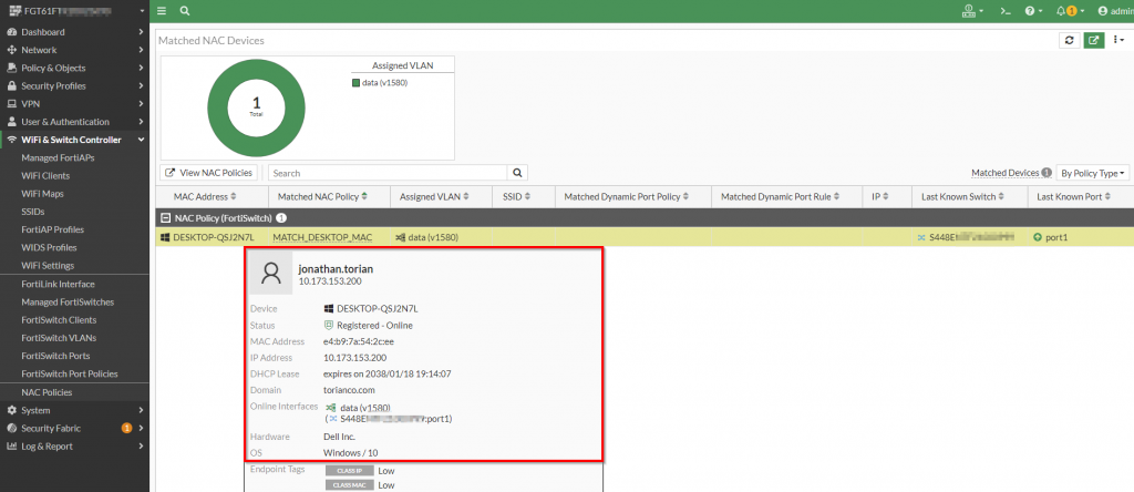
Figure 17. – Screenshot of information gathered by the FortiGate for the matched host
In addition to viewing the resultant match information in the FortiGate, there is also a corresponding log entry that contains this as well.
Verifying the Switch Controller Logs
A historical reference of the NAC policies being applied to connecting devices in the Fortinet infrastructure is recorded in the FortiSwitch logs. These logs can be sent to an external log aggregator like FortiAnalyzer or FortiSIEM. An example of what this log looks like is shown in the following screenshot:
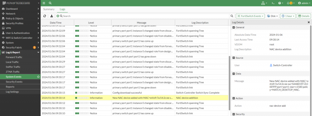
Figure 18. – Screenshot of the Switch Controller Log with the NAC Policy being matched
This article showcases the FortiGate/FortiSwitch NAC policies to perform matching based on the criteria defined about the devices. In the next article, I will cover performing network access control based on the user confirming their identity via a captive portal.